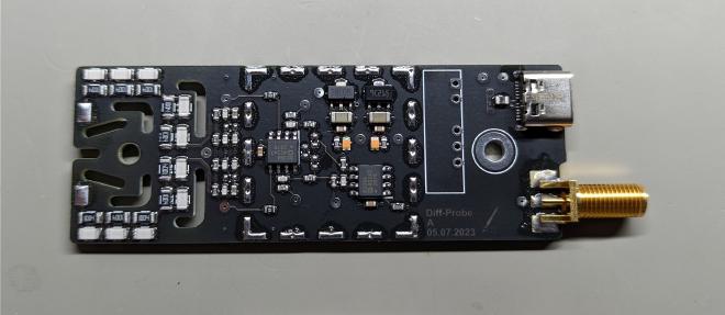
Diff Probe

Overview #
The goal of this project was to create a relatively cheap and simple differential probe, intended mostly for hobbyists and makers.
Specification #
This probe has a voltage rating of ±500V on each input, which means a differential rating of ±1000V.
Depending on the opamps the usable bandwith can be in excess of 10 MHz.
The power supply is done via a USB-C connector and a DC/DC converter for galvanic isolation.
I’ve tried two different opamps, with whom the Diff-Probe can reach the following bandwidths:
| Opamp | Opamp bandwith | Probe bandwidth | Cost per opamp |
|---|---|---|---|
| TL072 | 3MHz | ~1MHz | <0.20$ |
| AD8039 | 350MHz | ~18MHz | ~2.50$ |
Cost #
All the components cost about 20 to 25 USD with the more expensive opamp option. The other option is obviously quite a bit cheaper.
Housing #


Assembly of the Diff-Probe:

Files #
All the sources and output files can be found on my Github page.